Ion-Beam Analysis Techniques
For a detail discussion on Ion Beam Analysis (IBA) and the various techniques, please see IBA lecture by K. M. Yu.
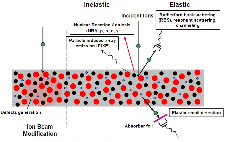
Figure 1 Schematic illustrating ion-beam-induced elastic and inelastic-scattering reactions.
MeV ion-beam analytical techniques
- Rutherford backscattering spectrometry (RBS)
- Particle induced x-ray emission (PIXE)
- Elastic recoil detection analysis (ERDA)
- Ion channeling spectrometry
- Resonant scattering and nuclear reaction analysis (NRA)
Applications of ion-beam analysis
-
Quantitative analysis of thin films:
- Thickness, composition, uniformity in depth;
- Solid state reactions;
- Interdiffusion.
- Quantitative measurements of impurities in substrates.
- Crystalline perfection of homo- and heteroepitaxial thin films.
- Defect distribution in single-crystal samples.
- Surface atom relaxation in single crystals.
- Lattice location of impurities in single crystals.
Strengths of ion-beam analysis
- Simple in principle.
- Fast and direct.
- Quantitative without standard.
- Depth profiling without chemical or physical sectioning.
- Nondestructive application.
- Wide range of elemental coverage.
- No special specimen preparation required.
- Can be applied to crystalline or amorphous materials.
- Simultaneous analysis with various ion beam techniques (PIXE, PIGMA, channeling, etc.).
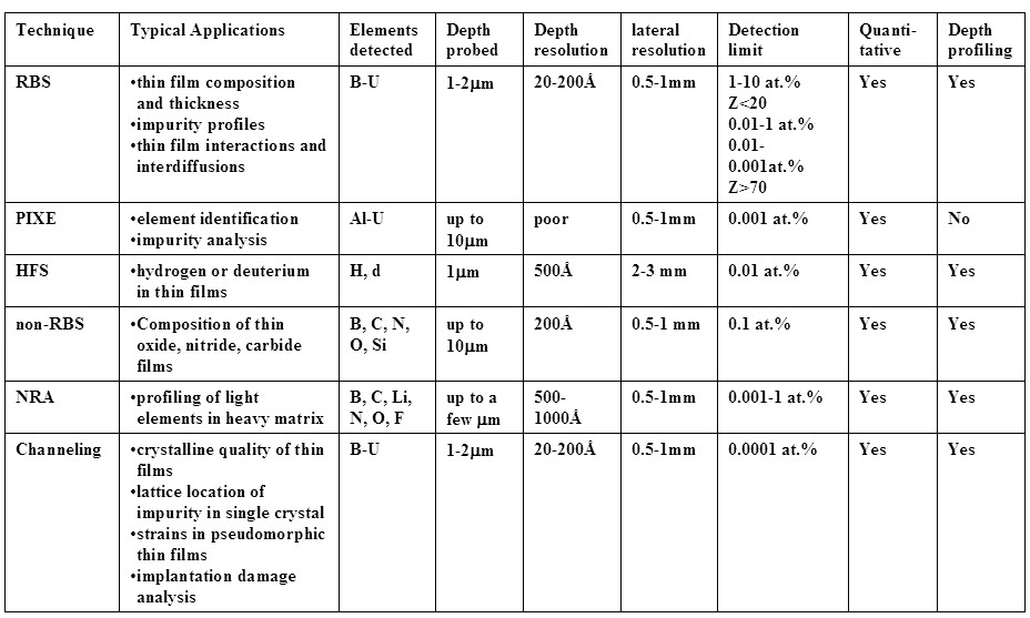
Table 1 Summary of various ion-beam analysis techniques.
Rutherford-backscattering spectrometry (RBS)
RBS detects the energies and amount of the backscattered ions from a solid target. The incident probe is a mono-energetic light ion beam, typically MeV He ions. The scattered He particles from the target are energy analyzed by a solid state particle detector (Si surface barrier detector) positioned at a backscattered angle with respect to the incident ion beam (typically ranging from 100°-170° depending on the specific analysis). The energy of the backscattered He ions are dictated by conservation of energy and momentum between the incident ion and the scattering atom and can be related to the depth and mass of the target. The amount of backscattered ions from any given element is proportional to its concentration. Therefore RBS can be used as a tool to investigate the depth profile of individual elements in a solid quantitatively.
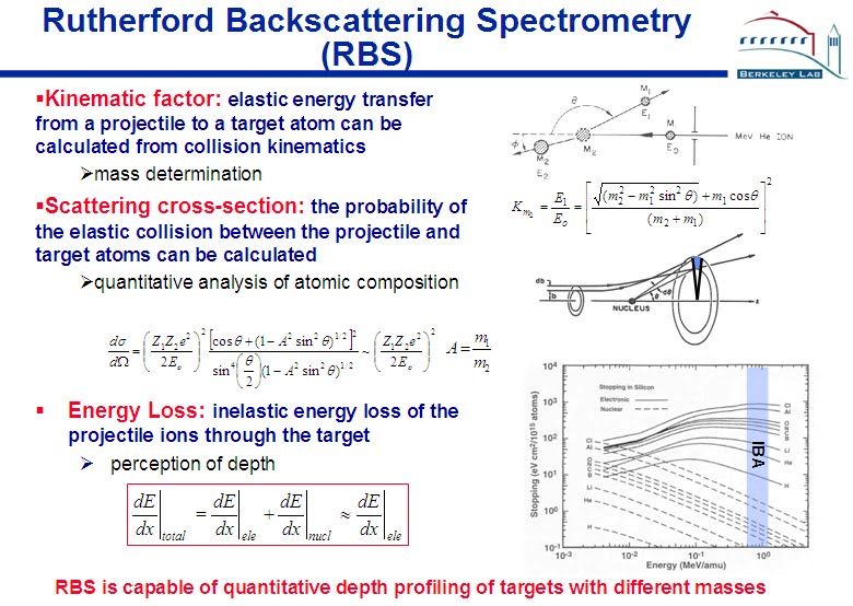
Figure 2
Particle-induced X-ray emission (PIXE)
PIXE is an analytical method which relies on the spectrometry of characteristic x-rays emitted by the target elements due to the irradiation of a high energy ion beam (typically 1-2 MeV of H or He). PIXE can identify various constituents in a compound target. Since there is little overlapping of the characteristic x-rays for different elements, simultaneous detection of complicated multi-elements sample is possible. Quantitative analysis is also possible with the appropriate corrections to absorption and x-ray yields. Trace element analysis using PIXE has a detection limit orders of magnitude lower than can be attainable by x-ray spectrometry techniques using electron excitation. Under favorable conditions, a detection limit ~1 ppm for thin foils and ~10 ppm for thick samples can be achieved. PIXE has been successfully applied to solving problems in many different fields, including corrosion and oxidation, semiconductors, metallurgy, thin films, geoscience, air pollution and atmospheric science, biology, medicine, art, archaeology, water analysis, and forensic science.
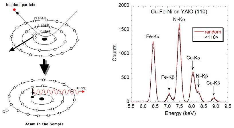
Figure 3
Elastic Recoil Detection Analysis (ERDA)
When a MeV He ion beam incident on a sample with H and D, the H and D in the sample will be scattered in the forward direction. Spectrometry of these forward recoiled atoms gives rise to the quantitative depth profiling of these species in the sample. Elastic-recoil scattering (ERS) provides a unique method for measuring the H and D content in thin films with detection limit ≥ 0.01%. Because of the relatively small energy loss of H in solid, the depth resolution of this method is typically ~300-600 Å. ERS is also called elastic recoil detection (ERD) or forward recoil spectrometry (FRS).
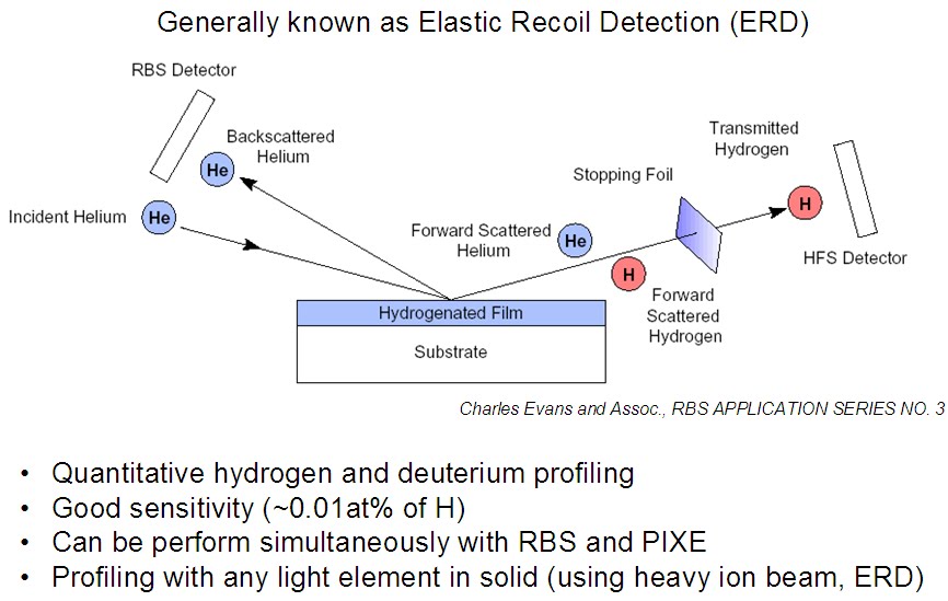
Figure 4
Non-Rutherford backscattering spectrometry (NRBS)
In RBS one assumes a pure Coulomb process in which scattering occurs between two completely unscreened nuclear point charges. When the collision diameter is very small and becomes comparable to the sum of the nuclear radii of the projectile and the target atom, the finite sizes of the nuclei and the nuclear force interactions lead to deviations from the Rutherford scattering cross section. For MeV ion beams, this phenomenon can be observed in low Z projectile/target system where the Coulomb barrier is small. The cross-section for such nuclear resonance scattering can be many times greater than the Rutherford values. Such non-Rutherford scattering has been used to some extent for the detection of light elements (C, N, O, Si) in heavy matrices
Nuclear reaction analysis (NRA)
When an energetic particle hits a nucleus in a target, depending on the mass of the particle and target and the energy of the particle, a variety of final products may form. RBS is a special case in such reaction in which the reaction products are the same as those before reaction. In cases where the incident beam energy exceeds a certain threshold value, other energetic particles appear in the spectrum. The detection of these particles usually provide information which is not obtainable from RBS. The NRA technique is very useful as a tool for the detection and profiling of light elements in heavy matrix. In many cases such particle-particle NRA can be carried out in a RBS setup with only minor modifications.
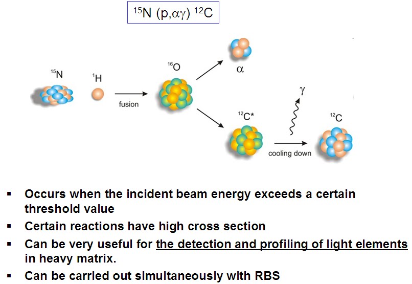
Figure 5
Ion channeling
When an ion beam is well aligned with a low index crystallographic direction of a single crystal, e.g <100> of Si, there is a >95% reduction in the yield of small impact parameter interactions processes, namely RBS, PIXE and NRA. RBS and PIXE measurements in the channeling orientation are therefore, ideal for providing crystallographic information on radiation damages, crystal defects, impurity location in single crystals and strains in superlattice structures. The ion channeling process can be modeled in terms of ion scattering from atomic strings (axial channeling) or planes (planar channeling) with uniform continuum potentials. Using this continuum model, quantitative analysis is also possible.
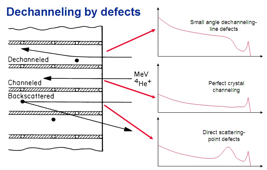
Figure 6
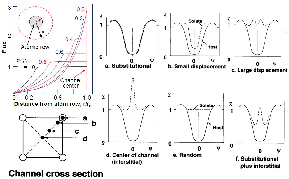
Figure 7 Lattice location of impurities.
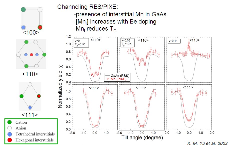
Figure 8 Channel cross section.